Showing posts with label circuitpython. Show all posts

Friday, February 5, 2021

Raspberry Pi Pico

Raspberry Pi Pico

Micro Python:

1. Open Source
2. Modules are cheaper 	

Circuit Python :

1. Fork of Micro Python 
2. Owned by Ada Fruit
3. Compatible with Only Ada Fruit Modules
4. Expensive 
5. No ConCurrency and No State Sharing 

Pre- Req:

  1. Download the below files Micro Python / Circuit Python
    1. Micro Python (Recommended) - MicroPython
    2. Circuit Python UF2 file from - https://circuitpython.org/board/raspberry_pi_pico/
  2. Hold Raspberry Pi Pico on-board BOOTSEL button (Button on the board)
  3. Plug it into USB (or pulling down the RUN/Reset pin to ground)
  4. It will appear as a USB disk drive
  5. you can copy paste the firmware onto drive
  6. the drive will change for Circuit python and no reaction for Micro Python

Micro Python :

  1. Install and open thonny IDE
  2. IDE should automatically detect pico

Shell

from machine import Pin
led = Pin("LED", Pin.OUT)
led.value(1)
led.value(0)

Code - save as main.py in "MicroPython" device

from machine import Pin
import time
led = Pin("LED", Pin.OUT)  # Pin(25, Pin.OUT)
for i in range(1, 5):
    print(i)
    led.value(1)
    time.sleep(1)  # Use 1 second instead of 10 seconds for better visibility
    led.value(0)
    time.sleep(1)

Circuit Python :

Configure Mu Editor so that Code can be seen running in real time., ie as soon as the code is saved , the result reflected in LEDs directly .

  1. sudo apt-get update
  2. sudo apt-get -f upgrade
  3. apt install libfuse2
  4. Download and Install Mu Editor

Run

  1. Copy paste below program into code.py
  2. Save the file in the device
  3. Open Mu Editor
  4. Should automatically recognise PICO and Opens code.py

Blink Program

import board
import time
from digitalio import DigitalInOut, Direction,Pull
led = DigitalInOut(board.LED)
led.direction = Direction.OUTPUT
#Connect LED between Pin1 ie GP0 and Pin 2
op = DigitalInOut(board.GP0)
op.direction = Direction.OUTPUT

while 1:
    if led.value==0: led.value= True
    elif led.value==1:led.value = False
    time.sleep(0.5)
    
    if op.value==0: op.value= True
    elif op.value==1:op.value = False
    time.sleep(0.5)

Input Switch

    import time
    import board
    import digitalio
    button = digitalio.DigitalInOut(board.GP0)
    button.switch_to_input(pull=digitalio.Pull.UP )
    while True:
            print(button.value)
            time.sleep(0.5)

https://learn.adafruit.com/getting-started-with-raspberry-pi-pico-circuitpython/blinky-and-a-button https://www.youtube.com/watch?v=nYA4PVljE4Q

view raw micropython.md hosted with ❤ by GitHub

Sunday, January 31, 2021

CIRCUITPYTHON :SEEEDUINO XIAO [SEED]

 CIRCUITPYTHON :SEEEDUINO XIAO

Steps:

 Uses SAMD21 Processor

1. connect SEEEDuino xiao to PC using TYPE-C cable
2. short RST pins using a cable fast , 2 times.
3. Once done successfully,Audrino drives appears
4. Go website -

https://circuitpython.org/board/seeeduino_xiao/

https://wiki.seeedstudio.com/Seeeduino-XIAO-CircuitPython/

5. Download latest .UF2 file
6. Copy and paste it inside the drive
7. Now the drive will be converted to CIRCUITPY
8. Create a file code.py
9. Copy paste below code into code.py (same for all circuit py IC)

import time
import board
from digitalio import DigitalInOut,Direction


led = DigitalInOut(board.D13) #D13 is a built in LED

#A1 - A10 can be used as well if u use a separate LED and a Resistor 100 - 400 ohms refer below for calculations
led.direction=tinker .OUTPUT

while True:
    led.value = True
    time.sleep(1)
    led.value=False
    time.sleep(1)
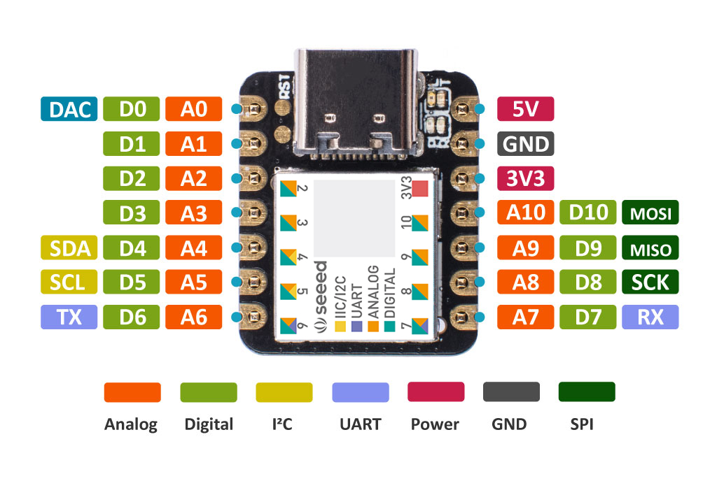


10. Save file
11. The LED should start blinking


A simple LED circuit consists of a LED and resistor. The resistor is used to limit the current that is being drawn and is called a current limiting resistor. Without the resistor the LED would run at too high of a voltage, resulting in too much current being drawn which in turn would instantly burn the LED, and likely also the GPIO port.

To calculate the resistor value we need to examine the specifications of the LED. Specifically we need to find the forward voltage (VF) and the forward current (IF). 

A regular red LED has a 

forward voltage (VF) of 1.7V 

 forward current of 20mA (IF). 

output voltage of the IC which is 3.3V.

We can then calculate the resistor needed-


RΩ=VI=3.3VFIF=3.31.720mA=80Ω


VI=3.3=3.31.7